Chapter8 (Part1)
Rods, having axial tensile or compressive forces are connected by cotter joints. Rods may be of different cross sections like circular or square. This is a temporary method of joining the rods. Cotter joints can be quickly assembled as well as disassembled.
A cotter is a rectangular cross section of uniform thickness and varying width with one of its longer sides tapered and other longer side being straight. The slots in the spigot rod and in socket are made slightly larger then the cotter with one side straight and the other side tapered. The taper on one of the sides of cotter facilitates holding of the two rods. Excessive taper must be avoided. For general use, a taper of 1:30 is recommended. When the taper is greater than 1:30, to prevent slipping back of the cotter, it should be locked in position by some additional means of locking arrangement.
8.2 Cotter Joint for Circular rods (Socket and spigot): Socket and spigot cotter joint is used to connect circular rods. One of the rods is formed into a socket by enlarging its end while the other rod, called spigot end is formed with enlarged diameter and an integral collar as shown in fig (8.1). The spigot is put inside the socket and the cotter is driven through the slots in socket and spigot ends. A pictorial view of socket and spigot cotter joint is shown in fig (8.1). While a sectional view of socket and spigot cotter joint is shown in fig (8.2). An exploded view of this joint is also shown here in fig (8.3).

Fig (8.1): Pictorial view of Socket and Spigot Cotter joint
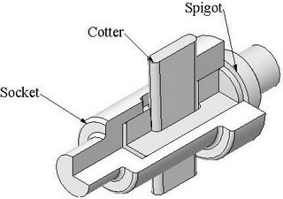
Fig (8.2): Sectional view of socket and spigot cotter joint
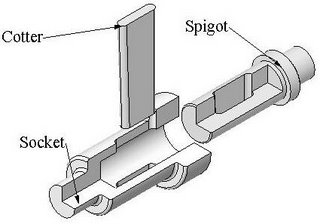
Fig (8.3): An exploded view of socket and spigot cotter joint
Components of socket and spigot cotter joint are shown below with typical dimensions. In fig (8.4), Pictorial and orthographic views of socket are shown. Similarly for spigot and cotter it is shown in fig (8.5) and in fig (8.6) respectively. Sectional isometric view and sectional orthographic views of Socket and spigot cotter joint is shown in fig (8.7) and in fig (8.8).

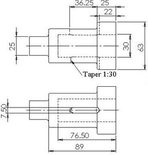
Fig (8.4): Pictorial and orthographic views of Socket


Fig (8.5): Pictorial and orthographic views of Spigot

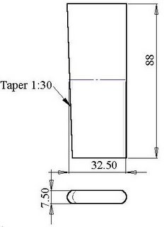
Fig (8.6): Pictorial and orthographic views of Cotter

Fig (8.7): Sectional isometric view of Socket and spigot cotter joint
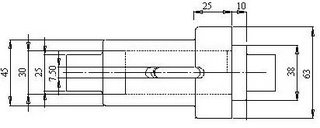

Fig (8.8): Sectional front view and top view of socket and spigot cotter joint
8.3 Cotter Joint for Round rods (Sleeve and Cotter Joint):
This cotter joint is also used to connect circular rods. This joint has better strength compared to the socket and spigot cotter joint. Here instead of a socket arrangement, a sleeve is used. Sleeve has two slots where two cotters are placed in different slots and going through different rods. A Pictorial view of sleeve and cotter joint is shown in fig (8.9). Half sectional and partial sectional views of sleeve and cotter joint are shown in fig (8.10).

Fig (8.9): Pictorial view of sleeve and cotter joint
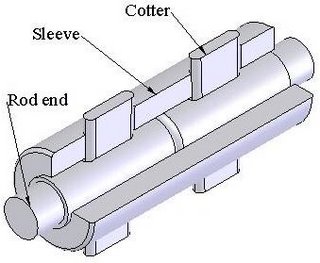
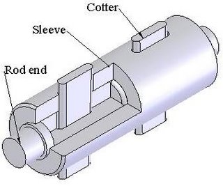
Fig (8.10): A half sectional and partial sectional view of sleeve and cotter joint
Components of Sleeve and cotter joint are shown below with typical dimensions. In fig (8.11), Pictorial and orthographic views of sleeve are shown. Similarly rod end it is shown in fig (8.12). Sectional orthographic views and Sectional isometric view of Sleeve and cotter joint are shown in fig (8.13) and in fig (8.14).
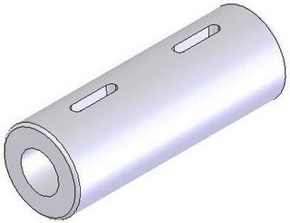
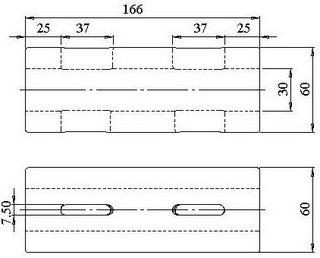
Fig (8.11): Pictorial and orthographic views of sleeve
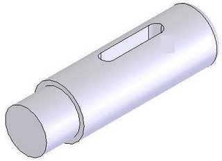
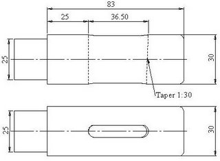
Fig (8.12): Pictorial and orthographic views of rod end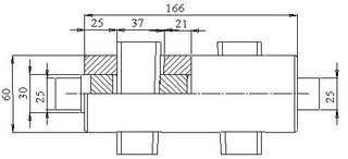

Fig (8.13): Sectional front view and top view of Sleeve and cotter joint
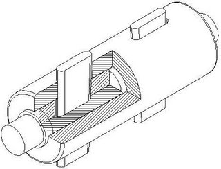
Fig (8.14): Sectional isometric view of Sleeve and cotter joint
![]()

