Chapter3 The Theory of Projections
Since engineers are confronted with the task of recording the sizes and shaped of three-dimensional objects on the plane of sheet of drawing paper, it is obvious that recognized procedure must be followed if their drawing and sketches are to be easily understood.
Objects are seen when light rays called visual rays, coming from the object strikes the observer’s eye. The size of the image formed on the retina will depend upon the position of the observer from the object. Such an image formed on the retina is called perspective view of the object. In the same way if an imaginary plane is introduced in-between the object and observer as shown in fig (3.1), the visual rays crosses at some points on the transparent plane. These points when connected form the perspective view of the object on an imaginary transparent plane. The imaginary transparent plane is called the plane of projection and the view formed on it is called projection. The visual rays are called projectors.
In the above case the view formed is called perspective projection.
3.1 Orthographic projections:
When the observer is at a finite distance from the object, the visual rays or the projectors converge to the eye. But if the observer is imagined at an infinite distance from the transparent plane or the plane projection, the projectors will be parallel and will be perpendicular to the plane of projection as shown in fig (3.1). This projection is called orthographic projection.
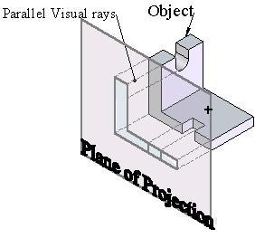
Fig (3.1): Orthographic projection of an object on projection plane
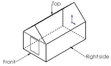

Fig (3.2): Principal Views of a Hut describing hut fully
A classification of projections has been shown through fig (3.3).

Fig (3.3): Classification of Projections
3.2 Principal views:
The orthographic projection shown in fig (3.1) does not describe the object fully. It only shows the appearance of the object when viewed from front. To describe the object fully, it should be viewed from different positions and the additional views should be projected on additional planes of projection as shown in fig (3.2). The figure shows the arrangement of planes to project the views from the front, top and right side of the object. These three mutually perpendicular planes of projection are called the principal planes and the views projected on these planes are called the principal views.
3.3 First and Third Angle Projections:
When a Cartesian co-ordinate system is extruded in z direction, it will take a shape of crossed planes as shown in fig (3.4). This has four quadrants, which can be numbered as first, second, third, and fourth quadrants in counterclockwise direction.
If the object has been put in first quadrant the object will be in-between the plane of projection and observer. So the front view is projected on the vertical plane and the top view on the horizontal plane. Now these transparent planes can be unfolded to make it on a drawing sheet. After unfolding the planes as shown in fig (3.6), the top view will be below the front view, right side view will be on left of the front view and the left side view will on right of the front view. This system of projection is called the first angle projection. Mostly first angle projection is used to draw orthographic views of components.
If the object has been put in the third quadrant as shown in fig (3.7), the plane of projection will be in-between the observer and the object. When the views are projected on the planes and the quadrant is unfolded. The top view will come on top of the front view, the left view will on the left of front view and right side view will be on right of front view. These views are shown in fig (3.8).

Fig (3.4): Cartesian Co-ordinate extruded to form Four Quadrants


Fig (3.6): Unfolded First quadrant


Fig (3.8): Unfolded Third Quadrant showing Orthographic projections.
![]()
![]()

