Chapter 4 (Part1)
To explain the "Projection of the axes" lets take a view of a cube so that its three principal faces are visible. Lets place a transparent sheet of glass in front of the cube and draw lines where the front edges of the cube meet at a point. The angle between adjacent edges of a cube is always 90º. After drawing the outline of the converging edges on the glass we can measure the angles between them. We can see that the angle between adjacent edges is greater than 90º in all three cases i.e. a>90º, ß>90º and g>90º. These are the angles between the projections of the axes. Theses axes are known as the axonometric axes. If the angles between all the axes are same then this view is known as isometric view (i.e. a = ß = g =120º ). If two of the angles are the same then it is known as diametric view (i.e. a = ß ¹ g). And finally if all three angles are different a trimetric view results (i.e. a ¹ ß ¹ g )

Fig (4.1)-(A) A cube showing angles between projection of axis a, b & g. (B) Isometric projection of cube where a = b = g = 1200. (C) Isometric axes.
4.2 Foreshortening:
The concept of foreshortening is a very important one in isometric projection. Let us take two orthographic views (first angle i.e. elevation above, plan below) of a pencil, which is parallel to the ground, and take a view perpendicular to its length shown in fig (4.2). In its starting position the pencil is a true length in both plane and elevation. Holding the pointed end of the pencil steady move the opposite end away from you, ensuring the pencil remains parallel to the ground. Keep moving the pencil away from you until you are looking along the point of the pencil. A view along the point of the pencil (a point view) is a view parallel to the direction in which the pencil is pointing. The length of the pencil changed as you moved it from full length to a point view. Every time you moved the pencil away from you its length appeared to get shorter or it foreshortened. As the pencil rotates parallel to the Horizontal plane its elevation becomes foreshortened. The further you move the end of the pencil away from you the greater the foreshortening. This is known as the degree of foreshortening.

Fig (4.2): Demonstration of concept of foreshortening by orthographic views of pencil.
4.3 Isometric scale:
We have seen how edges appear shorten (foreshorten) when a view is taken which is not perpendicular to them. So how do we obtain the length of a foreshortened edge in order to draw it on paper? A foreshortened line is a smaller or scaled down version of its true length. Hence, we need to generate a scale to establish the length of the foreshortened edges of an object so that it can then be drawn on paper. In isometric the three angles between the projections of the axes are equal, so the degree of foreshortening along each of the axes is the same. Isometric means "equal measure". This means that only one set of scales is needed to draw an isometric projection of an object. These scales can then be used to draw the edges of an object, which are parallel to the axes. How are these scales constructed?
A
B
CLet us take an isometric view of a cube. In order to see the true lengths of the edges that make up the top of the cube we need to rotate it until we are looking perpendicular to it. Lets rotate it about the line 'AC'. In its starting position line 'AB' made an angle of 30º with line 'AC'. However, in its final position, which shows the true lengths of the lines 'AB' and 'BC', line 'AB1' makes an angle of 45º with line 'AC'.
A scale is now constructed by stepping off true measurements along line 'AB1' which is a true length line. The measurements are then transferred back to line 'AB' to get a smaller scale, in this case an isometric scale (which is the same procedure used in the division of lines). Lines drawn using the isometric scale are approximately 80% of true size. This scale is usually marked off on a piece of paper and used to step off the foreshortened measurements along the projection of axes lines and lines parallel to them. Lines parallel to the projection of axes are known as isometric lines. Lines, which are not parallel to theses axes, are known as non-isometric lines. It is important to note that you can only use the scales on isometric lines.
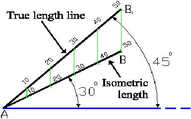
Fig (4.3): Isometric scale constructed by true length line
4.4 Isometric Projection vs. Isometric Drawing
When we draw an isometric projection of an object scales need to be constructed. These scales are used to measure off lines parallel to the isometric axes. Thus, a line drawn in isometric is smaller than its actual size (approximately 80% full size). If we draw an object in isometric but take the full edge length then the object would look simply greater then an isometric projection of the same object. This is known as isometric drawing.

Fig (4.4): Isometric Projection Fig (4.5): Isometric Drawing
Drawing of isometric projection starts with three isometric lines called axes, which represent three mutually perpendicular lines. One of these axis is drawn vertically and the other two at 300 with the horizontal on both sides of the vertical axis.
4.5 Non-isometric lines:
Edges whose projections are not parallel to one the isometric axes are called non-isometric lines. The one important rule is that measurements can be made only on the isometric lines and cannot be made on non- isometric lines. For example the diagonals of a face of a cube are non-isometric lines; although equal in length, their isometric projection lengths will not be equal.
There are two basic methods for drawing the non-isometric lines: the Boxing method and the Offset method.
4.5a Boxing method:
When object contains many non-isometric lines, it is drawn by the boxing method. When the boxing method is used, the object is enclosed in a rectangular box, which is drawn around it in orthographic projection. The box is drawn in isometric and object is located in it by its point of contacts as shown in fig (4.6). It should be noted that the lines, which are parallel on object, are also parallel in the isometric views. This knowledge can often be used to save a large amount of time as well as used for the test of accuracy.
Fig (4.6) is drawn by putting the top face into the isometric projection and drawing vertical lines equal in length to the edges downward from each corner. However it is not always necessary to enclose the whole object in a rectangular box. The pyramid may have its base enclosed in a rectangle and the apex located by making a vertical axis from the center and then joining the apex with the corners of the base.
Isometric projections of triangle, pentagon, hexagon etc can be made using boxing method, which will be discussed in detail subsequently.

Fig (4.6): Use of Boxing Method to draw isometric projection of Hexagonal Prism
4.5b Offset method:
When an object is made up of planes of different angles, it is better to locate the ends of the edges by offset method rather then by boxing method. When the offset method is used perpendiculars are extended from each to an isometric reference. These perpendiculars, which are isometric lines, are located on the drawing by isometric co-ordinates. The dimensions are taken from the orthographic view drawn on isometric scale. In fig (4.7) line AB is used as a baseline and measurements are made from it as shown, first to locate points on the base then verticals from these points E, F & G.
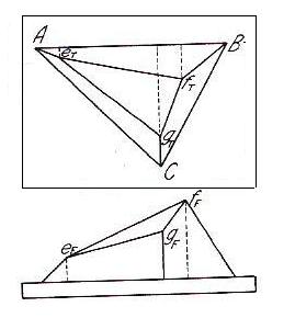
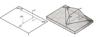
Fig (4.7): Isometric Projection of a model drawn by Offset method
4.6 Helping views to understand isometric projection:
4.6a. Isometric projection of triangle:
Step1: Draw an isometric Axis.
Step2: Draw triangle and enclose it by a rectangle of length a and width b.
Step3: Draw this rectangle on isometric axis. Where sides of rectangle are parallel to isometric axes.
Step4: Draw the triangle inside the rectangle on isometric axis by locating the contact points from the rectangle of step2.
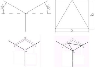
Fig (4.8): Steps for drawing isometric projection of Triangle. A) Step1, B) Step2, C) Step3, D) Step4
4.6b. Isometric projection of Pentagon:
Step1: Draw an isometric Axis.
Step2: Draw Pentagon and enclose it by a rectangle of length a and width b.
Step3: Draw this rectangle on isometric axis. Where sides of rectangle are parallel to isometric axes.
Step4: Draw the Pentagon inside the rectangle on isometric axis by locating the contact points from the rectangle of step2.

Fig (4.9): Steps for drawing isometric projection of Pentagon. A) Step1, B) Step2, C) Step3, D) Step4.
4.6c. Isometric projection of Hexagon:
Step1: Draw an isometric Axis.
Step2: Draw Hexagon and enclose it by a rectangle of length a and width b.
Step3: Draw this rectangle on isometric axis. Where sides of rectangle are parallel to isometric axes.
Step4: Draw the Hexagon inside the rectangle on isometric axis by locating the contact points from the rectangle of step2.
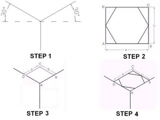
Fig (4.10): Steps for drawing isometric projection of Hexagon. A) Step1, B) Step2, C) Step3, D) Step4
![]()

