Chapter2 (Part2)
2.1h Drawing sheets:
There are standard sizes of drawing sheets. The basic principle involved in deciding the size of drawing sheet is described below.
a) x : y = 1 : 1.41
b) x y=1
Where x and y are the sides of sheet and having a surface area of 1m2.
By above equation x = 0.841m and y = 1.189
Halving along the length or doubling along the width obtains two series of successive format sizes. The areas of the two sizes are in the ratio of 1:2. The sizes of the trimmed sheets are given below in table2.1 and shown in fig (2.8). Drawing sheets may be used with their longer sides positioned either horizontally or vertically. The general features of a drawing sheet are shown in fig (2.9).
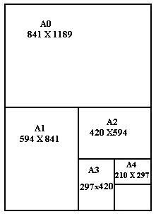
Fig (2.7): Drawing sheet dimensions
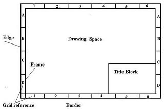 Fig (2.8): Drawing sheet with features
2.1h(1) Title block
The title block should be within the drawing space such that the portion of the title block containing the identification of the drawing (title, origin, Id. no. etc.) is situated in the bottom right-hand corner of the drawing space both for sheets positioned horizontally or vertically. Title block consist one or more adjoining rectangles. These may be sub-divided into boxes for the insertion of specific information.
2.1h(2) Borders and frames
Borders enclosed by the edges of the trimmed sheet and the frame limiting the drawing space shall be provided with all sizes. It is recommended that these borders have the minimum width of 20mm for size A0 and A1, and a minimum 10mm for the size A2, A3 and A4.
2.1h(3) Grid references
The provision of grid reference system is recommended for all sizes, in order to permit easy location on the drawing of details, additions, modifications, etc. the number of divisions should be divisible by two and be chosen in relation to the complexity of the drawing. The rectangles of the grid should be referred by means of capital letters along one edge and numbers along the other edge.
Table 2.1: Drawing Sheet dimensions
Designation Dimension (mm)
A0 -----------841 X 1189
A1 -----------594 X 841
A2 -----------420 X 594
A3 -----------297 X 420
A4 -----------210 X 297
2.2 Lines (Conventional line symbols):
In engineering drawing, lines of different thickness, type and lengths are used to describe the object. Different types of lines are shown in fig (2.9) and the application of lines is shown in fig (2.10).
2.2a Visible outline:
All the visible edges and the surface boundaries of an object, known as outlines are drawn as thick continuous lines as shown in fig (2.9). So that the shape of the object will be clearly visualized on the drawing.
2.2b Hidden lines:
The invisible edges and the surfaces of the object are drawn by broken lines as shown in fig (2.9) and these are termed as hidden lines. The hidden lines are drawn as thin line of short dashes of equal length of 2 to 3mm and spacing of about 1mm left in-between them.
2.2c Centrelines:
Centrelines are drawn to represent the axis of symmetry of an object and the circular features such as holes, cylindrical projections, pitch circle etc. They are drawn as thin chain lines of long and short dashes of proportions ranging from 6:1 to 4:1 alternatively and evenly spacing as shown in fig (2.9). The centerlines should extend a little beyond the view or the feature through which they are drawn.
2.2d Dimensions, Extension, Leader, & Hatching (Cross section):
The Dimensions, Extension, Leader, & Cross section lines are drawn as continuous thin lines as shown in fig (2.9).
2.2e Cutting plane lines:
The cutting plane are indicated by long chain thickened at the ends & thin elsewhere with alternatively long & short dashes of proportions ranging from 6:1 to 4:1 placed evenly as shown in fig (2.9).
2.2f Break lines:
The break lines are divided into two types of lines i.e. short & long break lines depending upon the length of the break. Short break lines are represented by the continuous wavy lines as shown in fig (2.9). While long break the ruled lines represent lines with short zig-zags placed at convenient distances shown in fig (2.9).

Fig (2.9): Conventional Line Symbols
Application of Different type of lines is shown in fig (2.10).
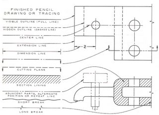
Fig (2.10): Application of different conventional Line symbols
![]()

