Chapter7 (Part2)
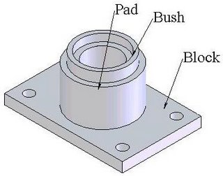
Fig (7.10): Pictorial Drawing of FootStep Bearing

Fig (7.11): Half sectional View of Footstep Bearing
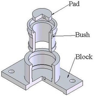
Fig (7.12): Exploded View of Half sectional Footstep Bearing
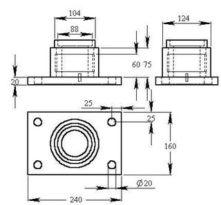
Fig (7.13): Orthographic Views (Front View, Top View & Side View) of Footstep Bearing
Exercise 3: Assemble the Components of Footstep bearing i.e. Pad, Bush & Block shown in fig (7.14), Fig (7.15) & Fig (7.16) and draw half-sectional front view of Footstep bearing.
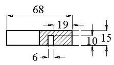
Fig (7.14): Half Sectional Front View of Pad
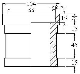
Fig (7.15): Half Sectional Front View of Bush

Fig (7.16): Half Sectional Front View of Block

Fig (7.17): Half Sectional Front View of Footstep Bearing

Fig (7.18): Sectional Isometric View of Footstep Bearing
7.5 Plummer-Block:
A plummer block consists of a cast iron Block Base, gunmetal bearing bottom & top halves, a cast iron cap and two mild steel bolts. It is made in two halves to provide easy placing and removal of the shaft in and from bearing. The split bottom & top halves give advantage to overcome wear as these can be easily replaced. The bolt holes in the block base are made longer with semi-circular ends for adjusting the position of the bearing. A half sectional pictorial view of plummer block is shown in fig (7.19) and an exploded sectional view of plummer block is shown in fig (7.20), which shows the positioning and assembling of parts in plummer block.

Fig (7.19): Half Sectional Pictorial View of Plummer-Block
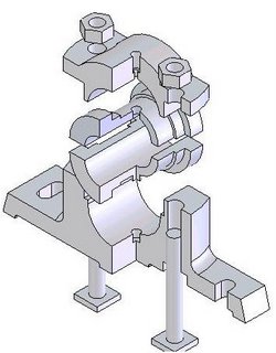
Fig (7.20): Exploded View of Sectional Plummer Block
Parts of plummer block are shown below. Fig (7.21) shows the sectional isometric view of cap while fig (7.22) shows orthographic views of cap. General dimensions of plummer block are taken to draw these figures. Fig (7.23) & Fig (7.24) shows the orthographic views of bearing top & bottom half respectively. The sectional front view and top views of block case is shown in fig (7.25). Assembling of all these parts results into plummer block which has been drawn in fig (7.26) and the sectional isometric view for the same is shown in fig (7.27).
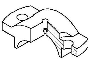
Fig (7.21): Isometric view of Cap
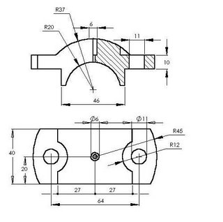
Fig (7.22): Half Sectional Front view and top view of Cap

Fig (7.23): Sectional Front View and Side view of Bearing Top half
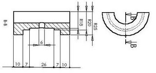
Fig (7.24): Sectional Front View and Side view of Bearing Bottom half
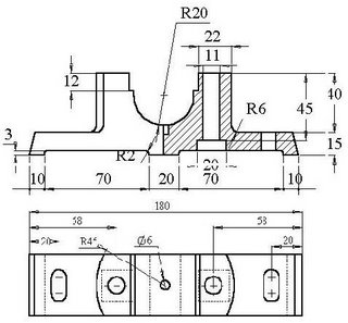
Fig (7.25): Sectional Front View and top view of Bearing Block Base
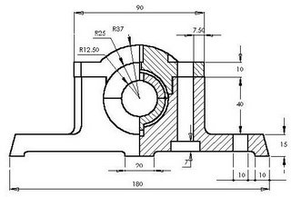
Fig (7.26): Half sectional front view of Plummer Block
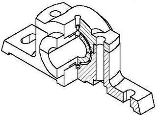
Fig (7.27): Sectional Isometric view of Plummer block
![]()

