Chapter7 (Part1)
Rotating shafts, which transmit motion and power, need to be supported on bearings. Long shafts, if supported only at its two ends, deflects at their centers. So for the smooth running of the shafts, bearings are used at some intervals.
In good bearings, provisions for lubrication and easy replacement of worn-out surfaces are offered. The bearings are generally used in supporting the spindle of machine tools, crankshaft of engines, axles of automobiles; shafts in workshops etc. to fulfill these wide requirements in different conditions, different shapes and structures are used. Bearings are grouped under two categories, namely, sliding contact bearings and rolling contact bearings.
In sliding contact bearing, the relative motion between the shaft and the bearing surface is of pure sliding. Due to the surface contact, the friction between surfaces of rotating shafts and the bearing is relatively high. So to minimize this friction, lubrication is used between two surfaces.
Sliding contact bearings are also classified as
1. Journal bearing (Radial bearing)
2. Thrust bearing
Journal bearings are used to support shafts that are subjected loads perpendicular to shaft axis. The portion of the shaft supported by the bearing is called journal.
Thrust bearings are used to support shafts subjected to axial loads.
Open bearing comes under the category of journal bearing, which is a sliding contact bearing. A pictorial drawing of open bearing is shown in fig (7.1). A full sectional and a half sectional view of open bearing are shown in fig (7.2).

Fig (7.1): Pictorial Drawing of Open Bearing
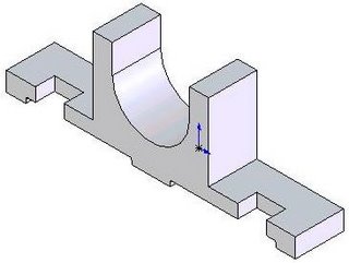

Fig (7.2): Full and Half Sectional View of Open bearing
Exercise 7.1: Draw the Half sectional Front view, Top view, Side view & Sectional isometric view of open bearing shown in fig (7.3).
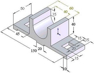
Fig (7.3): Isometric view of Open bearing

Fig (7.4): Half Sectional Front view, top view, side view & Sectional Isometric view of Open bearing
7.3 Bushed bearing:
It is a modification of solid bearing. A bush of brass or gunmetal is press fitted inside the bearing. Shaft sits on the bush instead directly in contact with bearing. A grub screw or a pin inserted half inside the bush and half in the block prevents sliding or rotating of bush against bearing. The basic purpose of bush is that when bush gets worn out, it can be easily replaced instead replacing the whole bearing. The boltholes in the block are made longer with semi-circular ends for adjusting the position of the bearing. A pictorial drawing of bushed bearing is shown in fig (7.5) and a half sectional pictorial view is shown in fig (7.6).
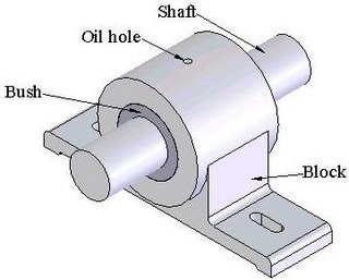
Fig (7.5): Pictorial Drawing of Bushed Bearing with Shaft
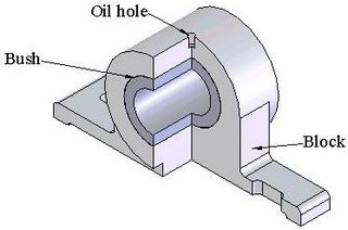
Fig (7.6): Half sectional Pictorial view of Bushed Bearing

Fig (7.7): Half sectional Isometric view of Bushed Bearing
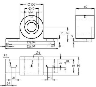
Fig (7.8): Orthographic Views (Front view, Top view & Side View) of a typical Bushed Bearing
Exercise 2: Draw the Half sectional Front view, Top view, Side view & Sectional isometric view of Bushed bearing Shown in fig (7.8) by orthographic views.

![]()

