Chapter 6
Sectional views are used to clarify interior or hidden details on an Orthographic projection of an object. A sectional view usually replaces one of the principle views (top, front or side) but may also be an additional view or a series of supplemental views depending on the type.

Fig (6.1): Sectional view of a component cut by a cutting plane
6.2 Types of sectional view:
There are many types of sectional views: Full, Half, Removed, Revolved (Rotated), Aligned, Offset, Broken-out, Partial, Assembly and Pictorial. These have been explained below.
6.2a Full Sectional view:
A Full Sectional view is used to show the object as if one half of the object was removed. The example below shows a simple single plane sectional view where object is cut in half by the cutting plane
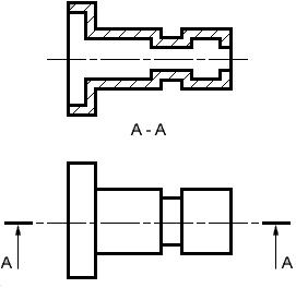
Fig (6.2): Full Sectional View
6.2b Half Sectional view: A Half Section view is used to show the object as if one quarter of the object was removed.
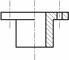
Fig (6.3): Half Sectional view
6.2c Removed Sectional view: A Removed Sectional view is used to show the variable shape of the object from end to end.
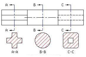
Fig (6.4): Removed Sectional view
6.2d Offset sectional view:
The section planes are usually assumed to pass through the axis of symmetry or the principal axis of the object. When several features like holes, slot, recess etc of the component do not lie on the axis of symmetry of the object the section plane may be offset, as shown in fig (6.5) to include the axes of different features.

Fig (6.5): Offset Sectional View
6.2e Aligned Sectional view:
An Aligned Sectional view is used to show the shape of features that do not align with the vertical and horizontal centerlines of the object.

Fig (6.6): Aligned Sectional view
6.2f Broken-out Sectional view:
A Broken-out Sectional view is used to show the material thickness of a hollow object.
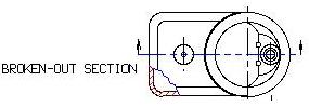
Fig (6.7): Broken-Out Sectional view
6.2g Partial Sectional view: A Partial Sectional view is similar to a Broken-out but usually covers a larger area but less than a Half Section. It is common practice to section a part of an object when only small areas need to be sectioned to indicate the important details.

Fig (6.8): Partial Sectional view
6.2h Assembly Sectional view:
An Assembly Section is used to show the arrangement and relationship of parts that makeup an object.

Fig (6.9): Assembly Sectional View
6.2i Pictorial Sectional View: A Pictorial Section is used to show the arrangement and relationship of parts that makeup an object in a three dimensional view with a quarter to a half of the object removed.

Fig (6.10): Pictorial Sectional view
6.3 Cutting Plane representation:
Sectional views are located by creating a Cutting Plane Line in one view. The Cutting Plane Line is a thick, dark line composed of a long dash, two short dashes and a long dash. An optional Cutting Plane Line consisting of thick, dark, long dashes may also be used. Short perpendicular lines with arrowheads pointing away from the line are added to each end to indicate the viewing direction or line of sight. The arrows should also point away from the view that is sectioned. Identification "Letters" (A-A, B-B, C-C, etc.) should be placed above the arrows when more than one section view is needed on a drawing.

Fig (6.11): Representation of Cutting Plane Lines
6.4 Hatching:
"Section Lining" or "Cross Hatching" or "Hatching" is added to the Section view to distinguish the solid portions from the hollow areas of an object and can also be used to indicate the type of material that was used to make the object. General Purpose "Section Lining", which is also used to represent "Cast Iron", uses medium, thick, lines drawn at a 45° angle and spaced 1/8" apart. Different materials have different patterns of lines and spacing. Section lining should be reversed or mirrored on adjoining parts when doing an Assembly Section.
· To avoid confusion, "Hidden Lines" are omitted from Section views.
· Spokes (that are used to hold the rim and hub of a wheel together) and ribs (that are used to reinforce or support a hub and a plate) are not sectioned.
· Keys, key ways, nuts, bolts and other fasteners on Assembly Sections are not sectioned.
![]()

