3.4 Projection symbols:
The projection system used in drawing should be indicated in the title block of the drawing sheet. This can be shown by drawing the two views of a frustum of cone placed with its axis horizontal as shown in fig (3.9). The fig (3.10a) shows the symbol of projection for the first angle projection system and figure (3.10b) shows the symbol of projection for the third angle projection system.

Fig (3.9): pictorial view of Frustum of cone

Fig (3.10a): First Angle Projection symbol

Fig (3.10b): Third Angle Projection symbol
3.5 Orthographic views of Machine Parts:
When the object is given, its front, top and side views may be drawn by direct visualization. But generally instead of giving the object itself, its pictorial view will be given. A pictorial view is a 3D representation of an object. Since a pictorial view directly shows the shapes of the front, top and one the side face of the object, it will be easy to visualize the appearance of the object, when viewed from front, top and one of the sides. This enables the student to develop the technique of visualizing the external appearance of the object and ability to draw front, top and side views from the pictorial views.
Mostly this pictorial representation of an object is either isometric or oblique. In both these representations the object may be visualized. For example a circle is shown in pictorial view as elliptical, similarly a rectangle as a parallelogram.
The following rules can be studied carefully and understood thoroughly before making attempt to prepare an orthographic drawing.
1) The front and top views are always in line vertically as shown in fig (3.11).
2) The front and the side views are in line horizontally as shown in fig (3.11).
3) The depth of the top view is the same as the depth of side views as shown in fig (3.11).
4) The width of the top view is same as the width of the front view as shown in fig (3.11).
5) The height of the side view is same as the height of the front view as shown in fig (3.11).
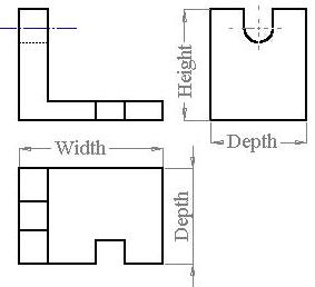
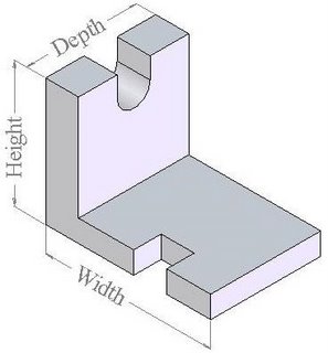
Fig (3.11): Orthographic projection of an object showing Width, Depth & Height
Problems
1. Isometric view of a corner block is shown in fig (3.12). Draw front view, top view and right side view of corner block in first angle projection.

Fig (3.12): Corner block
2. Isometric view of a Stop block is shown in fig (3.13). Draw front view, top view and right side view of corner block in first angle projection.
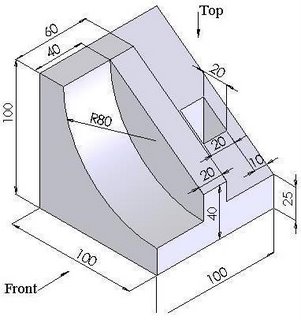
Fig (3.13): Stop Block
3. Draw orthographic views of parts shown in fig (3.14), Fig (3.15) and fig (3.16) below.

Fig (3.14)

Fig (3.15)
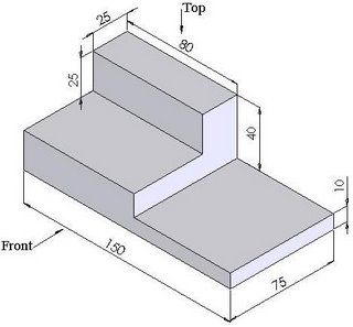
Fig (3.16)